System Components
Chapter 1 — Component-level architecture, inventory, working principles, and failure chain analysis
1.1 System Architecture
The explosion-proof video surveillance system is structured in three distinct tiers, each with clearly defined responsibilities and certification requirements. This tiered architecture ensures that all active electronics and computing resources remain in the safe area, while only certified Ex devices are deployed within hazardous zones. The deployment boundary is critical: the hazardous tier contains only devices with valid Ex certification suitable for the zone, gas/dust group, and temperature class. All servers, storage, and cybersecurity devices must be located in the safe area without exception.
Data and control flows are unidirectional where possible: cameras stream video to the VMS using RTSP/ONVIF or vendor protocols, which then writes to storage. Operator control commands flow from the VMS down to cameras. Alarm events flow from integration gateways to VMS actions such as preset positioning, bookmarking, and high-quality recording profile activation.
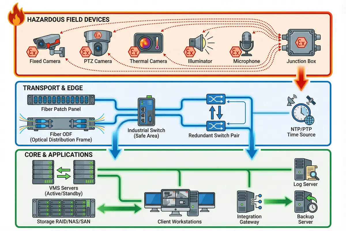
Tier Descriptions
- Hazardous Field Devices Tier: Contains only Ex-certified cameras (fixed, PTZ, thermal), Ex illuminators (only if required), Ex microphones (rare), and Ex junction boxes. Every device must carry a valid certificate matching the zone, gas/dust group, and temperature class of the installation location.
- Transport & Edge Tier: Comprises fiber patch panels, fiber ODFs, industrial switches located in the safe area, optional redundant switch pairs for ring topologies, and NTP/PTP time sources. Fiber is the mandatory transport medium from hazardous zones to the safe area.
- Core & Applications Tier: Houses VMS servers in active/standby configuration, storage systems (RAID/NAS/SAN), client workstations, integration gateways for F&G/SCADA/access control, log servers, and backup servers. All components in this tier are standard IT/OT equipment operating in the safe area.
1.2 Components & Functions
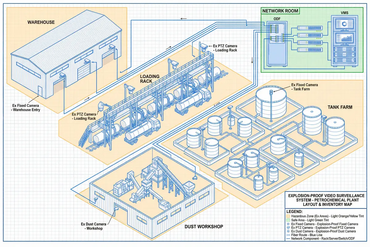
The component inventory map below illustrates how different device types are distributed across a typical plant layout, including tank farms, loading racks, warehouses, and dust workshops. Each component type has defined inputs, outputs, key quantitative indicators, and typical mismatch risks that must be understood during the design and procurement phases.
| Component | Responsibility | Inputs | Outputs | Key Quantitative Indicators | Typical Mismatch Risk |
|---|---|---|---|---|---|
| Ex Fixed Camera | Area overview, identification | Power, network, time sync | H.264/H.265 streams, metadata | Min illumination ≤0.01–0.05 lux; WDR ≥120 dB; IP66/67; operating -40 to +60°C | Wrong zone rating; incorrect T-class → ignition risk; insufficient WDR → glare loss |
| Ex PTZ Camera | Long-range inspection, presets | Operator commands, alarms | Stream + PTZ telemetry | 25–40× optical zoom; preset time <2s; pan/tilt accuracy ±0.1° | Moving parts wear; wrong mounting causes vibration blur |
| Ex Thermal Camera | Leak/temperature anomaly assist | Power, network | Thermal stream, alarms | NETD ≤50 mK; spectral range 7.5–14 µm | Misinterpreting thermal as safety sensor; lens contamination in dusty areas |
| Ex Junction Box | Safe termination in-zone | Field cables | Segregated connections | Certified glands; terminals rated for current/voltage; IP66+ | Non-certified glands create ignition path |
| Fiber Backbone | Intrinsically spark-free transport | Patch cords | Optical link | 1G/10G; ring recovery <50–200 ms (if ERPS) | Fiber bend loss; improper termination increases attenuation |
| Safe-Area Switches | Aggregation, VLAN, QoS | Fiber uplinks | VLAN trunk | Backplane capacity; PoE budget (if used); port density | Using PoE in wrong zone; no QoS → video loss |
| VMS Server | Management, recording, users | Streams, alarms | Recording, live view | CPU/GPU capacity; failover RTO/RPO; concurrent streams | Undersized compute → dropped frames |
| Storage | Retention, evidence | Recording writes | Playback, exports | RAID level; IOPS; retention days (7–30 typical) | Wrong RAID policy; no export integrity |
| Time Sync (NTP/PTP) | Forensic timeline | GNSS/clock | NTP/PTP | Offset <50 ms target; stratum level | No time sync → evidence disputes |
| Integration Gateway | Alarm linkage | F&G/SCADA events | VMS actions | Event latency <1–3 s; protocol support (OPC UA, Modbus) | Wrong mapping causes wrong camera pop-up |
1.3 Working Principles
The system operates through a defined sequence of states from startup through normal operation to abnormal recovery. Understanding these operational principles is essential for both commissioning engineers and O&M personnel to ensure the system performs reliably and maintains its explosion-proof integrity throughout its service life.
Startup Sequence
The correct startup sequence is: HAC verification → Ex certificate check → installation inspection → power-on sequence (safe-area first) → link validation → VMS enrollment → baseline recording test. This sequence ensures that no hazardous-area equipment is energized before the safe-area infrastructure is confirmed operational and all Ex compliance checks are complete.
Normal Operation
During normal operation, the system provides continuous monitoring with scheduled recording and event-triggered actions including preset positioning, bookmarking, and export locking. The VMS health monitoring subsystem continuously checks link status, device temperatures, storage capacity, and recording integrity, raising alarms when thresholds are exceeded.
Abnormal Scenarios & Recovery Chains
- Fiber cut in hazardous route: Ring protocol re-routes traffic (if designed) → VMS raises "camera unreachable" alarm → operator dispatches maintenance team with certified tools → post-repair attenuation test and evidence log required.
- Camera overheating due to sun load: Camera internal temperature alarm → VMS triggers lower bitrate/preset pause (if supported) → maintenance team adds certified sunshade or relocates camera → verify T-class margin remains adequate after modification.
- VMS server failure: Standby VMS node takes over within RTO target → recordings continue on remaining nodes → failed node investigated and rebuilt from golden image → credentials reset and evidence integrity verified before returning to service.
- Storage degradation: VMS raises storage health alarm → retention policy temporarily reduced → exports prioritized for critical evidence → failed disk replaced under change management procedure → RAID rebuild monitored to completion.
Certification & Compliance Chain
Every component in the hazardous zone must maintain an unbroken compliance chain. This means that the camera body, cable glands, conduit seals, junction boxes, and all maintenance activities must each individually comply with the applicable Ex standard for the zone. A single non-compliant element — such as an uncertified cable gland — breaks the entire explosion-proof chain and creates an ignition risk, regardless of the compliance status of all other components.